Table of Contents
VFX 101 with Mayu
I wanted to make this VFX video and post to explain the process of making a VFX from the ground up. I found that most of the tutorials online were very scattered and not in a linear fashion where you start from the very basics and slowly climb the ladder.
As I am also new to this, I will keep updating the posts with changes and new updates to make it better as I get better.
1. Basics of UV coordinates
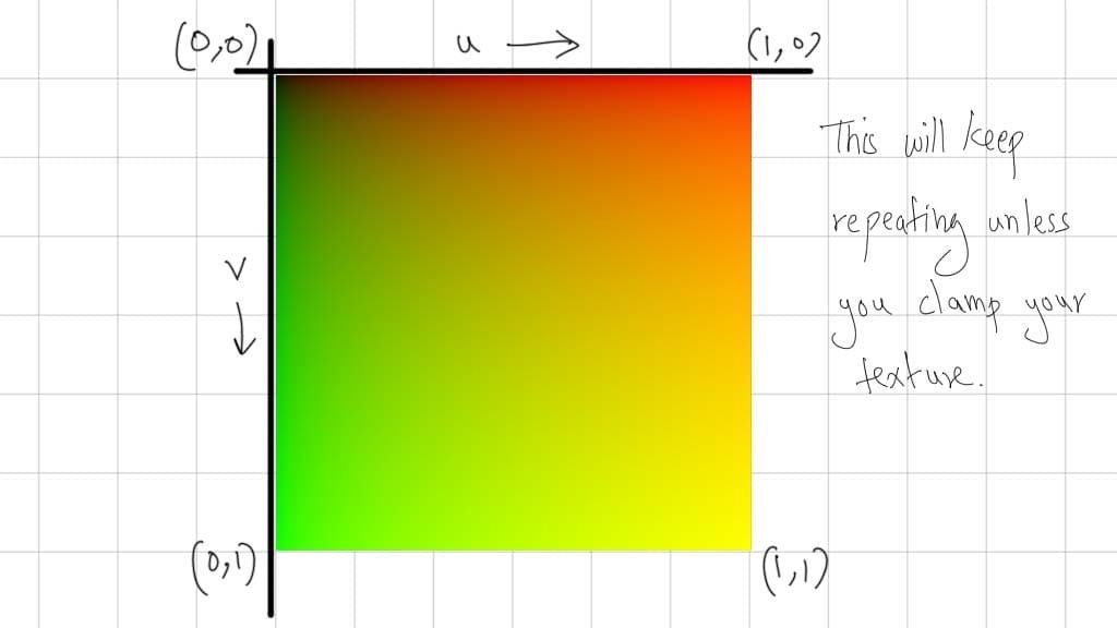
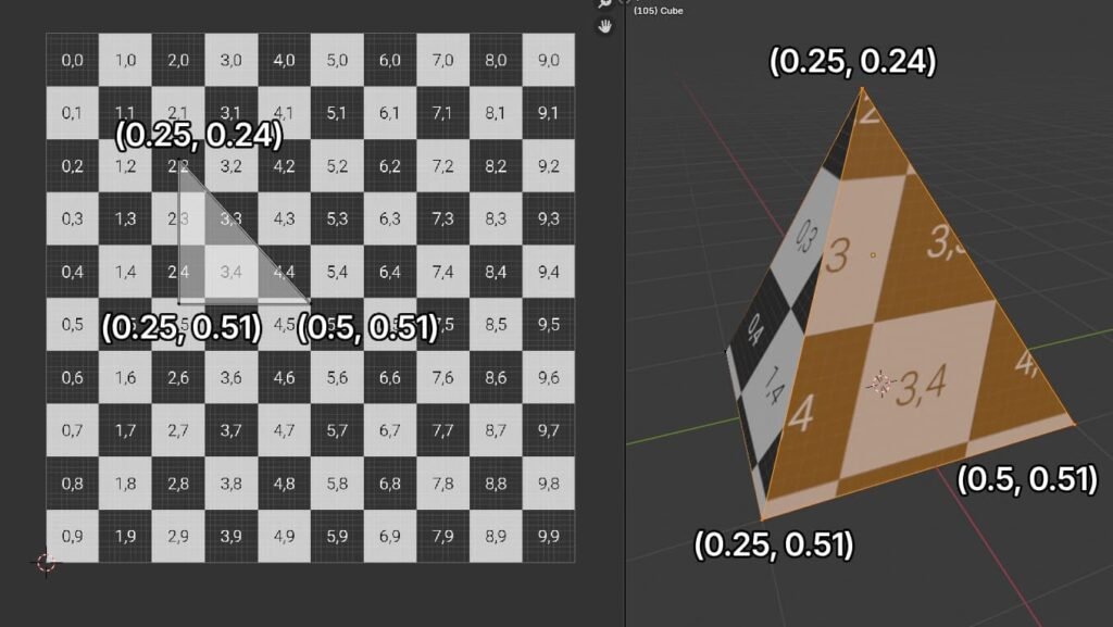
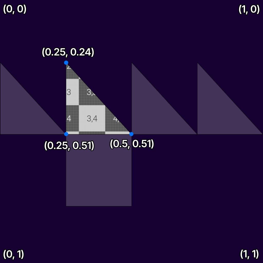
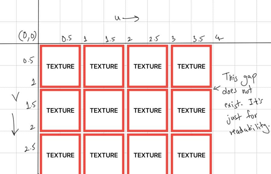
UV coordinates are basically XY coordinate but are named “UV” to not confuse them from XYZ coordinates in 3D. The below UV mapping is from Unreal Engine, so if you’re using Unity or other game engine, the mapping will simply be flipped vertically. All theory below works for all engines.
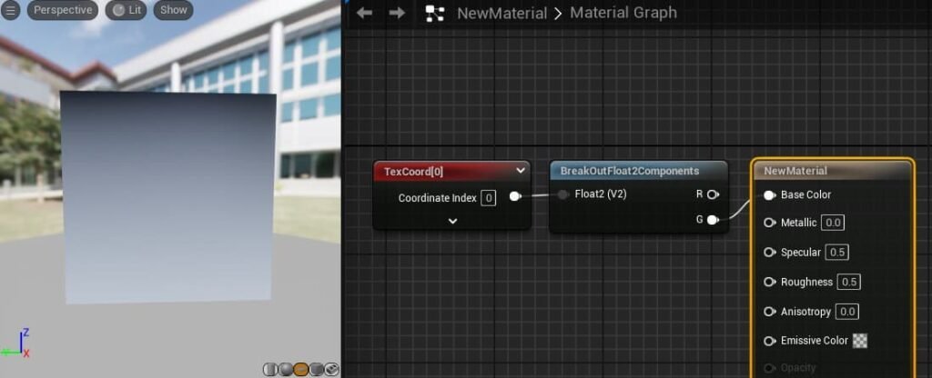
To check UV mapping in your software, simply attach Texture Coordinate node to base color in your material and check it on square plane.
2. Isolating U and V axis
As we know UV is just XY coordinates, we can isolate U and V for control over specific direction/axis. In Unreal Engine, there are multiple nodes to isolate UV. You can use “componentmask” node and select only R channel to isolate U or you can select only G channel to isolate V.
My favorite way is to use “breakoutfloat2component” node.
Don’t stress out if the letters on node look different.
To give you an example: float1 is single number(decimals included) – (0.2) , float2 is (0.2 , 0.5), float3 is (0.5, 0.6, 0.7). The color uses RGB channels, so basically it is float3 as 3 numbers are used. UV is float2 as 2 numbers are used, Transform properties like location, scale, rotation each use 3 numbers for each axis so it is float3.
So even if you see XY, UV, RGB on nodes. They simply mean multiple float values, so when you try to isolate each float number, some nodes might say XY, RGB and all, but it doesn’t matter what they say. What matters is how you use this values in your material/shader.
3. Tiling Textures using Multiply node
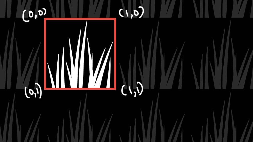
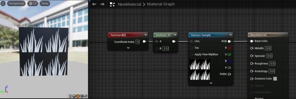
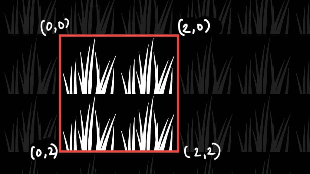
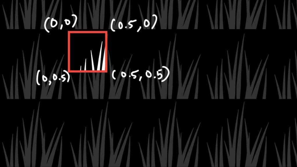
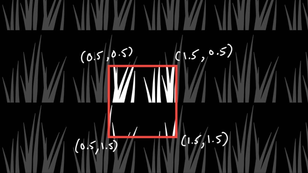
As we know our UV coordinates by default are (0,0) (0,1) (1,0) (1,1) as shown in point (1), if we multiply this values by 2, the new values are (0,0) (0,2) (2,0) (2,2). Similarly if we multiply default coordinates with 0.5, which is similar to dividing by 2, we get (0,0) (0,0.5) (0.5,0) (0.5,0.5).
By default, our textures are set to repeat. This allows us to tile texture.
Note: Texture Repeats in all directions including the negative values left and top in below graph. For visual purposes, I only showed positive side.
The below image is UV(TexCoord) multiplied by 1. This does no change.
The below image is UV multiplied by 2. The image is now tiled twice.
The below image is UV multiplied by 0.5. The image is now 1/4th the size.
4. Tiling Textures in specific axis (U or V)
In below image, we break TexCoordinate(UV) into U and V channel, then we separately tile in each axis. As TextureSample requires UV value i.e float2 value, we have to combine U and V values again.
With right values and right texture, you can create a stretchy pattern that can be used for waterfall, power beams and many more.
5. Offsetting/Panning Textures using add node
If we isolate U and V channels from UV coordinates, we can offset/pan in one axis. Example: In below image, we offset U by 0.5 and V by 0.
In below image, we offset V by 0.5 and U by 0.
6. Time node
We don’t really use time for tiling(using multiply) as it will keep increasing and make texture way too dense as time goes by. But if you still use it then after multiply add a “frac” node, it basically removes single digit from a float number, Example: as time goes by 0:00, 0:01, 0:02 … 0:99, 1:00, 1:01 … 1:99, 2:00 and so on, if we use frac after this, it will simply remove the single digit and only keep decimal numbers. This will lead to repeat of 0.00 – 0.99 numbers, creating a pulse kinda effect.
To control speed, we can simply multiply time with a number. Example: if time is going is 0,1,2,3,4… If we multiply it with 2, the speed will be double going 0,2,4,6,8…
Similarly, if we multiply it with 0.5 or divide by 2, the time will go 0, 0.5, 1.0, 1.5, 2.0 ….
This way our output value changes and allows use to control speed of our desired effect.
Using negative value changes the direction.
To compress it a bit, Unreal Engine already has a “Panner” node. You can simply use Speed X and Y for direction and speed. But for tiling we still need to multiply it our texture. In below image, I have isolated U and V to tile them separately but you can just use 1 if you don’t want control over single axis.
7. Grayscale Texture
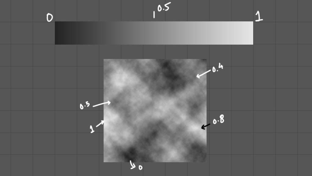
In below image we have added grayscale noise texture to opacity channel. This makes the mesh opacity 0 wherever there is pure black and opacity 1 wherever there is pure white, rest of the values are between 0 and 1 which are gray in color.
Tip: In unreal, you have to choose your material type, in below case I have chosen “Translucent”. This enables the opacity pin and allows us to use transparency. The other options are masked and additive. Masked blend mode does not provide translucency for gray color, it is good for textures that have pure black or white values. You can think of it as only having options of 0 , 1 and no 0.3 , 0.4 etc.
Note: In below texture, I am using a packed texture. It basically contains 3 different grayscale textures in each channel, R, G and B. So, if you check in below image, I have only connected R channel, that means I am only using the grayscale texture stored in R channel. There are plenty of videos showing how to pack multiple textures in 1 image.
8. Combining Textures (Add, Subtract and Multiply)
We have learnt about tiling and offsetting UV with add and multiply node. But now we learn how adding, subtracting and multiplying 2 textures work.
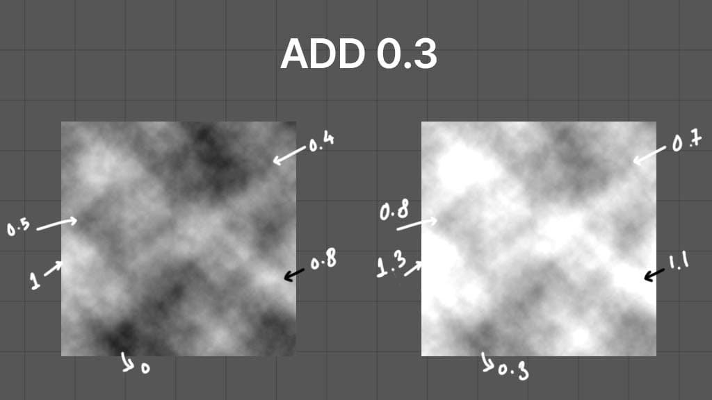
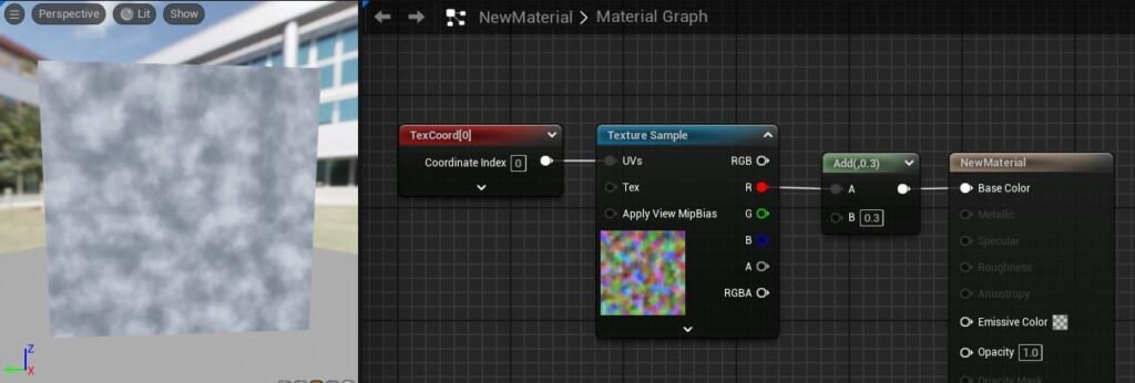
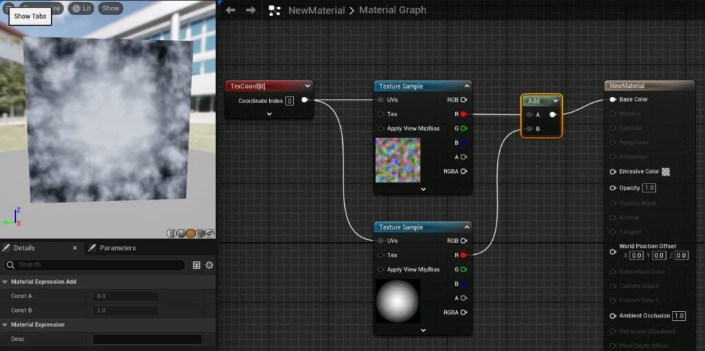
In below image, left is grayscale texture in which we add 0.3. The right image is the result of that math. You can see that our texture has gotten more brighter and that is simply because our pixels on texture are added by 0.3. (Use above grayscale bar to understand better).
Similarly if you subtract a number, it will get darker. Using Add/Subtract can help you create erosion of texture effect.
Note: As you can see our values are over 0 and they can also go below 0 if you do subtract. Depending on where you’re using this texture, it would be important to clamp the values between 0 to 1 using clamp node. OR you can use “saturate” node that also does clamping between 0 to 1. Basically, all values over 1 are made into 1 and all values below 0 are made into 0.
If we add two textures, then each pixel of both textures do addition with their respective values. You can see that wherever there is black in 2nd texture, the value is 0. So the result in that area is just the first texture as it was added with 0.
If we subtract right texture from left, then the each pixel value from right is subtracted from corresponding pixel value from left texture. If the right texture has black pixel, then it’s value is 0. This would lead to no change as we are subtracting by 0. If the right texture has white pixel, then it’s value is 1. This would make the corresponding output pixel to be black as the output pixel will be 0 or lower. (Make sure to clamp values from 0 to 1)
Subtracting helps to create corrosion effect.
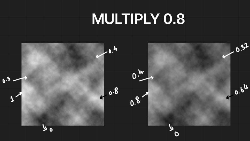
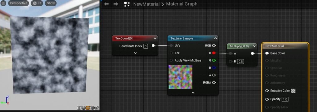
In below image, you will see different effect than add/subtract. As we are multiplying with 0.8, we are essentially using 80% of the left values which leads to lower values and darker texture.
But one important thing you can see is that, Multiplying with 0 will give us 0. This essentially allows us to use textures as mask for each other and combine each other.
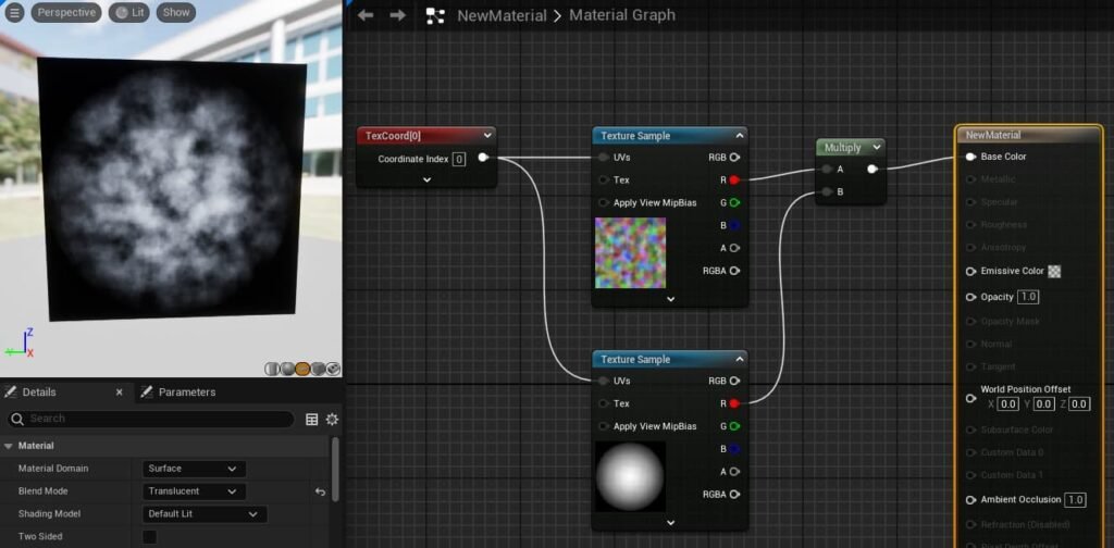
If we multiply textures, then each pixel of both textures multiply with their respective values. You can see wherever there is black in any one of the texture, the value is 0 and anything multiplied with 0 gives 0. So the result looks like a combined mask.
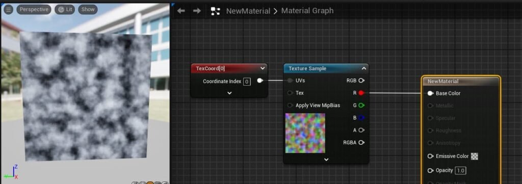
Unreal Engine Implementation – Default Texture with no math
Adding Value to a Texture (Using negative values will make it darker)
Multiplying Value to a Texture
Adding 2 Textures
Multiplying 2 Textures
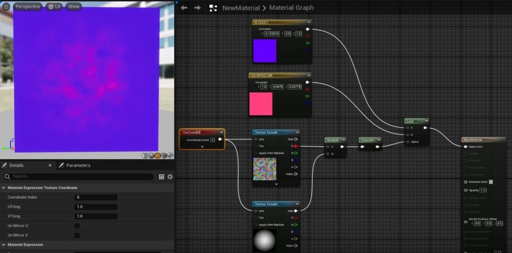
9. Using Textures with LinearInterpolate
This is not limited to just colors and you can use other texture/material on A and B pin to lerp between those.
10. Using Subtract to Create Erosion Effect
If you now pan the cloud texture in Y. We get this cool effect. Also keep in mind, I have connected the grayscale texture in opacity pin and not the lerp node. As opacity requires 0 to 1 value, we also have to provide it with 0-1 value grayscale texture.
Note: If you check in the live viewer, I have black background. Yours might show HDRI environment. To make the background black, simply go to Window –> Preview Scene Settings in top toolbar. This would add a new panel below, simply untick “Show Environment”.
You can see in below video, as we subtract higher values, more and more of our texture disappears. If somehow, we can increase this value from 0 to 1, then we can get erosion effect.
To simulate how corrosion would look over time, I have simply connected the “time” node, multiplied it with a low value for slower speed, and added the “frac” node. The frac node basically removes the left part of the decimal and keeps only the decimals.
So our time goes 0:00, 0:01, 0:02 … 0:99, 1:00, 1:01, 1:02… and so on. The frac node basically removes the left digits, so our output value would be 0.00, 0.01, 0.02… 0.99, 0.00, 0.01, 0.02… So you can see that it repeats. If you don’t use frac, we will start subtracting values higher than 1, which would just lead to a black texture.
Note: Frac helps to create looping animation. If you want something that disappears and does not show again, don’t use frac. A simple time node will do.
But when working with VFX, we don’t usually use time or frac for corrosion. We simply use a “dynamicparameter” node that allows us to control the value over the lifecycle of our particles from the Niagara system.
If I subtract my cloud texture from the radial gradient texture, I can get erosion effect. Keep in mind, that cloud texture is panning upwards. I also removed the multiply node (it is present in above video) as it worked in my case. But depending on what you want to do, you will need to play with all math nodes.


